


Recently, radiation intensity detection in living environments and water bodies has become a topic of widespread concern. In response to this demand, DWIN has specially developed and designed a radiation detector solution based on T5L_COF smart screens, and has open sourced the design for users to refer to.
Video: https://forums.dwin-global.com/index.php/forums/topic/%e3%80%90share%e3%80%91radiation-detector-solution-based-on-t5l_cof-smart-screen/
1. Detection principle
A Geiger counter is a counting instrument that specifically detects the intensity of ionizing radiation (a particles, b particles, g rays and c rays). The gas-filled tube or small chamber is used as the probe. When the voltage applied to the probe reaches a certain range, the ray is ionized in the tube to generate a pair of ions. At this time, an electric pulse of the same size is amplified and can be recorded by the connected electronic device. Thus, the number of rays per unit time is measured. In this program, the Geiger counter is selected to detect the radiation intensity of the target object.
Geiger Counting Tube Models Shell Material Recommended calibration factors (unit:CPM/uSv/hr) Operating voltage (unit:V) Plateau range
(unit:V) Background
(Unit:min/time) Limit voltage (unit:V)
J305bg Glass 210 380 36-440 25 550
M4001 Glass 200 680 36-440 25 600
J321bg Glass 200 680 36-440 25 600
SBM-20 Stainless steel 175 400 350-475 60 475
STS-5 Stainless steel 175 400 350-475 60 475
The picture above shows the performance parameters corresponding to different models. This open source solution uses J305. It can be seen from the figure that its working voltage is 360~440V, and the power supply is powered by a common 3.6V lithium battery, so a boost circuit needs to be designed.
2. Calculation principle
After the Geiger counter is in normal operation, when radiation passes through the Geiger counter, a corresponding electrical pulse is generated, which can be detected by the external interrupt of the T5L chip, thus obtaining the number of pulses, which is then converted into the required unit of measurement by means of a calculation formula.
Assuming that the sampling period is 1 minute, the measurement sensitivity is 210 CPM/uSv/hr, the measured pulse number is M, and the commonly used unit for measuring radiation intensity is uSv/hr, so the value we need to display is K= M/210 uSv /hr.
3. High voltage circuit
The 3.6V Li-ion battery is boosted to 5V to supply power to the COF screen, and then the COF screen PWM outputs a 10KHz square wave with a duty cycle of 50%, which drives the inductor DC/DC boost and back-voltage circuits to get 400V DC to bias the power supply to the Geiger tube.
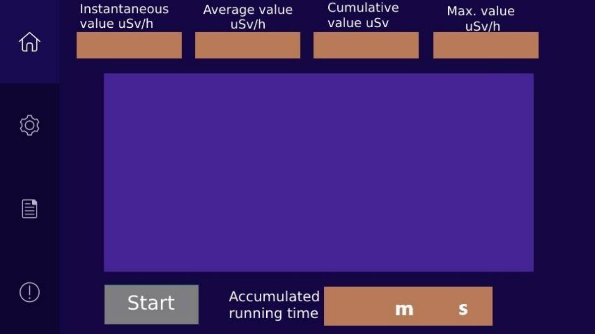
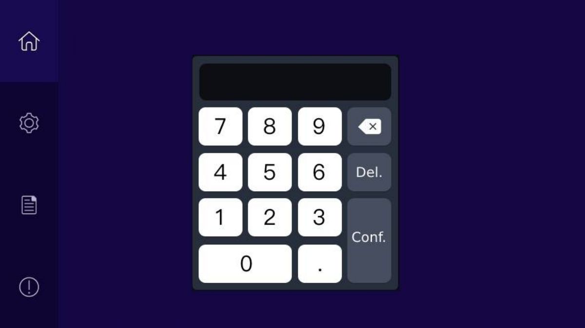
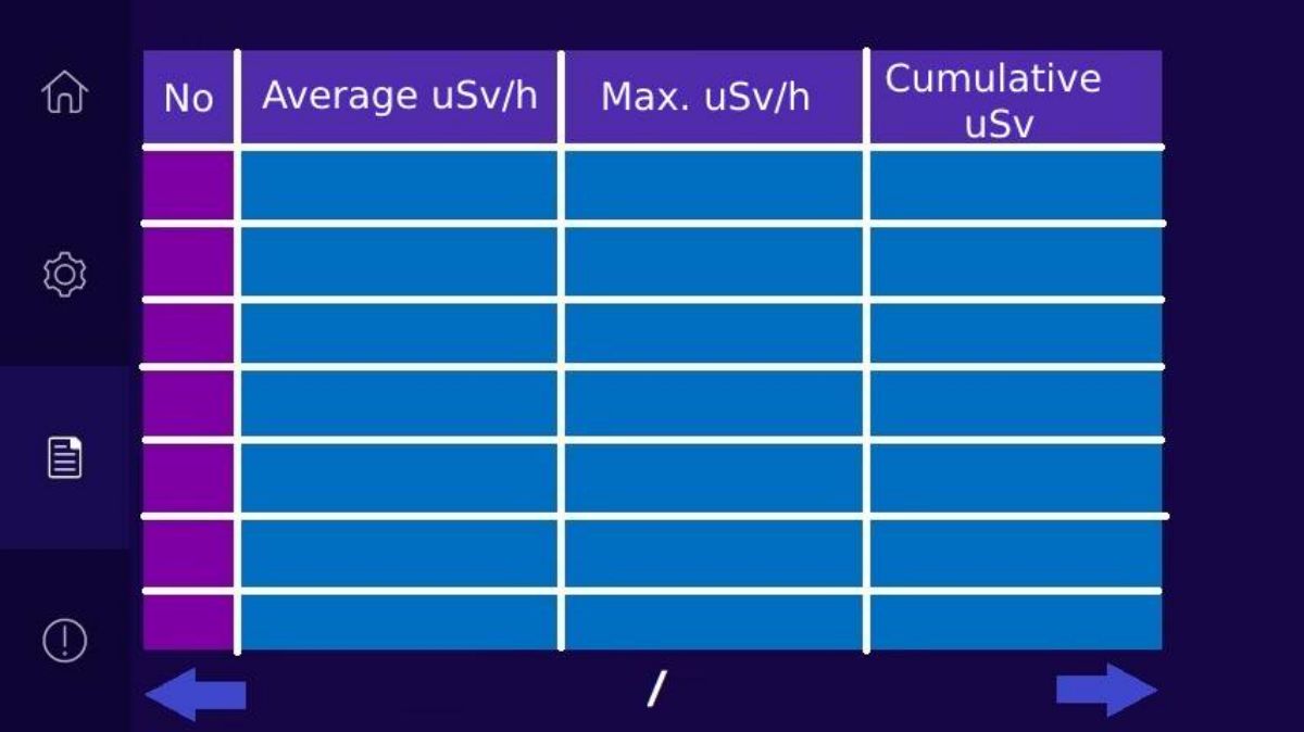
4.UI


Post time: Sep-06-2023