


1. Working principle
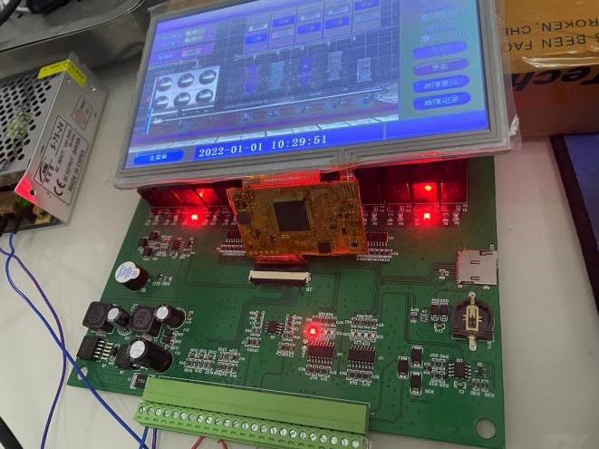
The solution uses the COF screen DMG80480F070_01WTR, which uses the T5L chip as the main control to receive and process the water supply data collected by the sensors, drive the LCD screen for data display and control the inverter to adjust the pump motor speed to achieve a constant and stable effect of the water supply system. There are abnormal warning and time-sharing water supply setting functions.
2. Scheme design
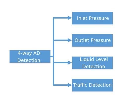
(1) Scheme block diagram
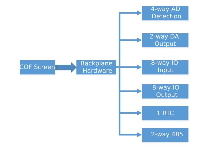
(2)Hardware block diagram
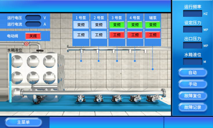
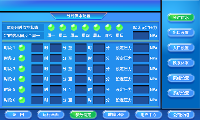
(3)DGUS GUI interface design
(4)Circuit Design
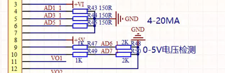
1.AD
Mainly collects conventional 4-20MA/0-5V sensors, converts the voltage-current type to 0-3V, and after AD calculation can obtain the corresponding sensor data.
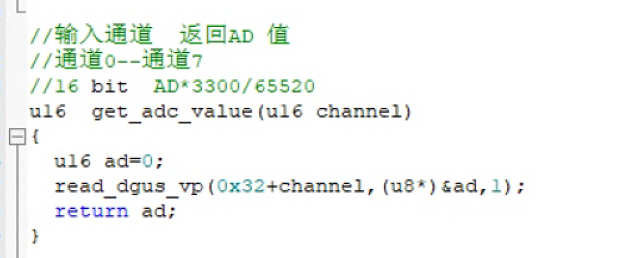
AD Reference Code
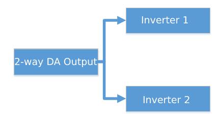
2.DA
The pwm is used to control the analogue voltage and outputs a 0-10V control signal through the op-amp.
DC detection schematic
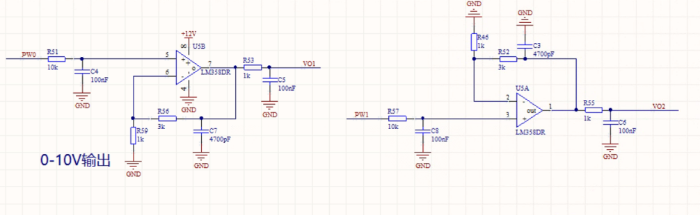
DC hardware schematic
DC Reference Code
3.IO input section
Mainly optocoupler inputs, T5L detects the corresponding level changes.
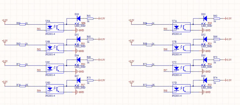
IO hardware schematic
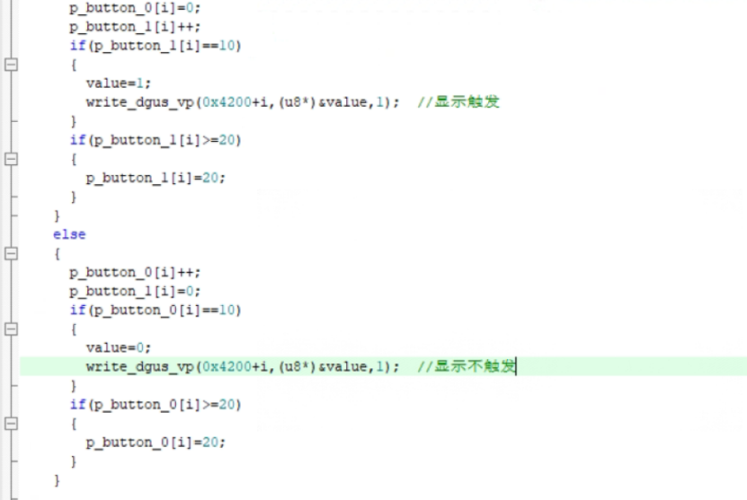
IO Input Reference Code
4.IO output
The IO main Darlington Transistor outputs control relays and the IO controls high and low levels.
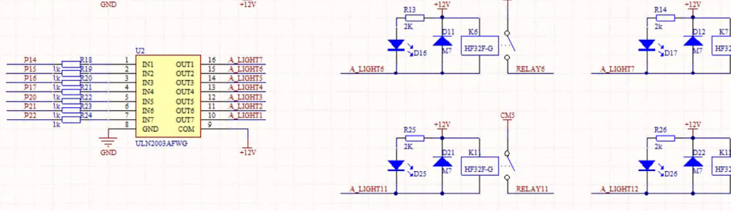
Relay Hardware Schematic
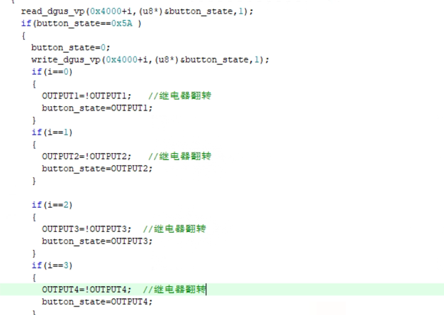
Relay Reference Code
5.RTC
RX8130, 2-wire communication.
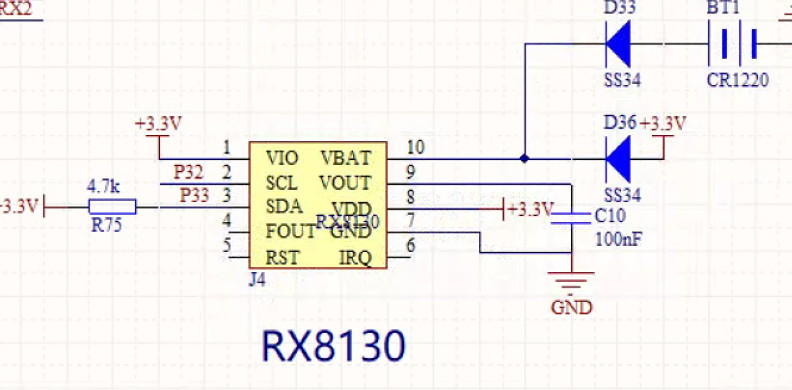
RTC Hardware Schematic
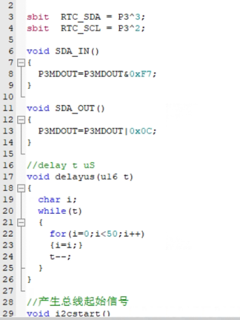
RTC Reference Code
6.485
Mainly use hardware to control the send and receive pins.
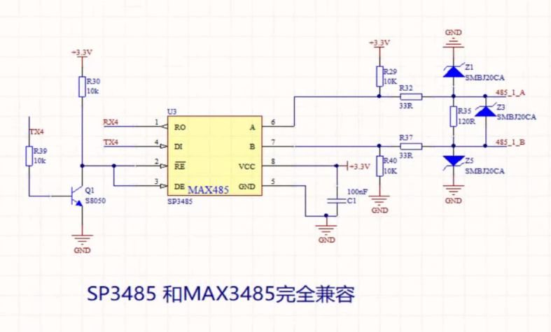
485 Hardware Schematic
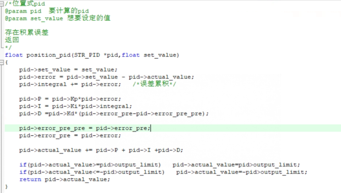
7.PID
The positional PID algorithm is mainly used, the output is limited, pay attention to the saturation of the integral term, and the result is to control the analog voltage for the PWM.
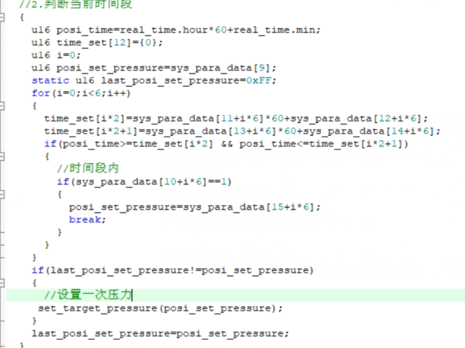
8.Other codes
Automatic setting of the start pressure according to the time.
Post time: Nov-30-2022