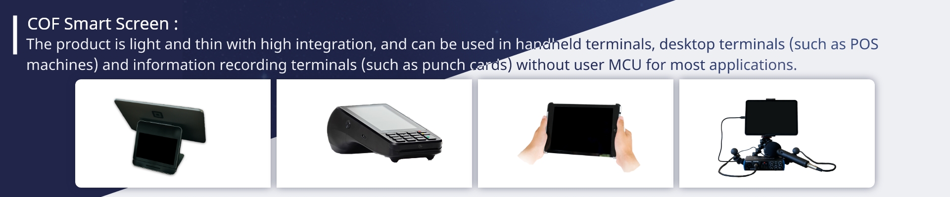
Specification
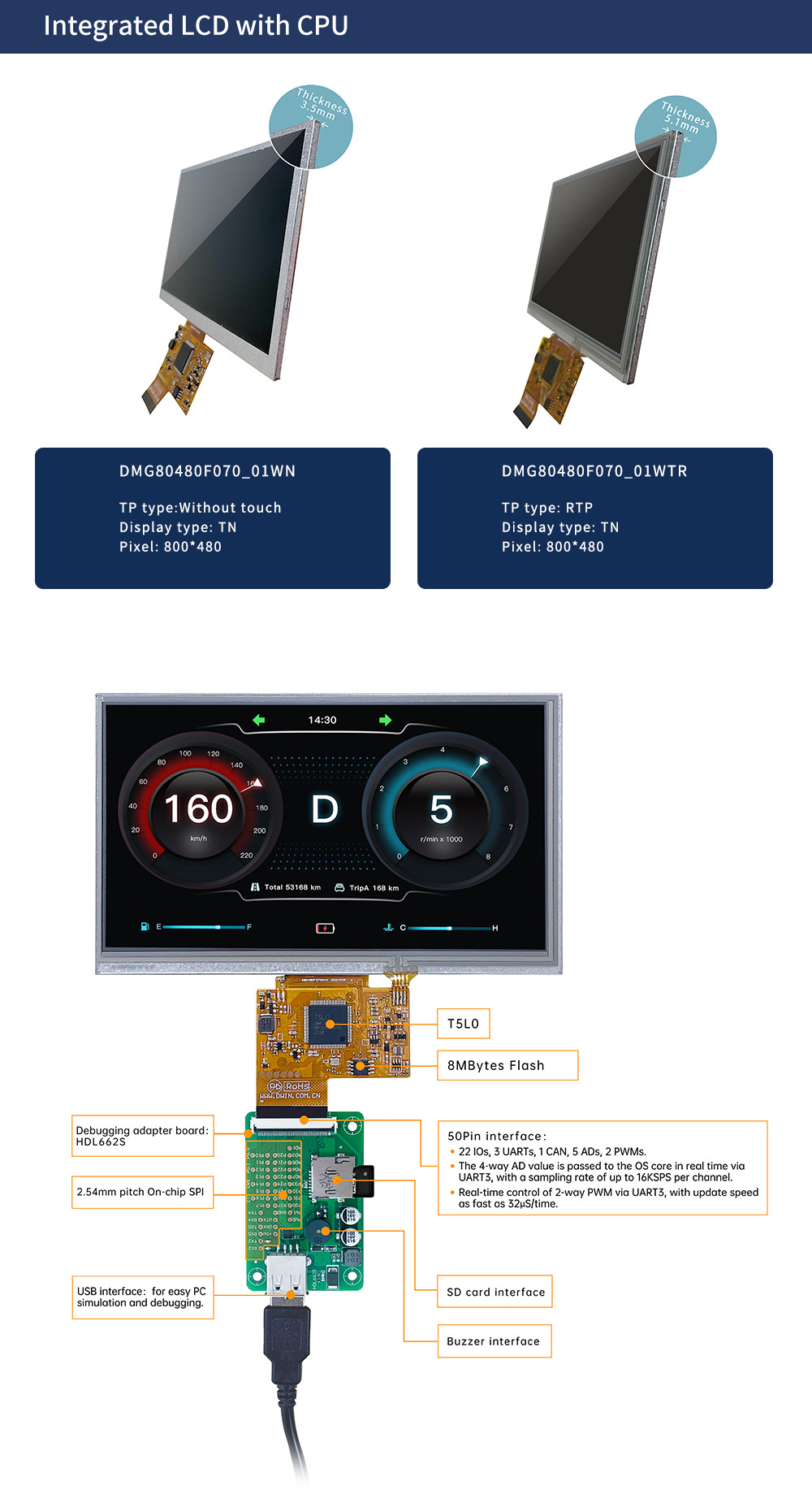
| T5L0 ASIC | Developed by DWIN. Mass production in 2020,1MBytes Nor Flash on the chip, 128Kbytes variable storage space for exchanging data with OS CPU Core and memory. Rewrite cycle: over 100,000 times | ||
| Color | 262K colors | ||
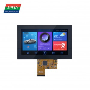
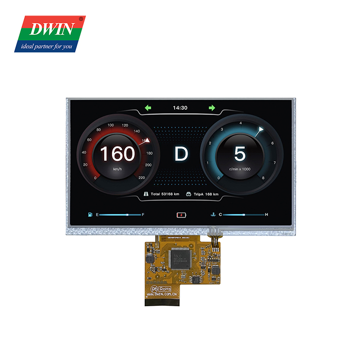
| LCD Type | TN, TFT LCD | ||
| Viewing Angle | Normal viewing angle, typical value of 70°/70°/30°/40°(L/R/U/D) | ||
| Display Area(A.A) | 154.08mm (W)×85.92mm (H) | ||
| Resolution | 800×480 | ||
| Backlight | LED | ||
| Brightness | DMG80480F070_01WN: 250nit | ||
| DMG80480F070_01WTR: 200nit | |||
| Type | RTP (Resistive touch panel) | ||
| Structure | ITO film + ITO glass | ||
| Touch Mode | Support point touch and drag | ||
| Surface Hardness | 3H | ||
| Light Transmittance | Over 80% | ||
| Life | Dotting > 1,000,000 times; Stroke > 100,000 times; 150g force, back and forth counted as twice |
||
| Power Voltage | 3.6~5.5V | ||
| Operation Current | VCC = +5V, Backlight on, 410mA | ||
| VCC = +5V, Backlight off, 115mA | |||
| Working Temperature | -10℃~60℃ | ||
| Storage Temperature | -20℃~70℃ | ||
| Working Humidity | 10%~90%RH, typical value of 60% RH | ||
| Baudrate | 3150~3225600bps | ||
| Output Voltage | Output 1, Iout = 8mA; 3.0~3.3V | ||
| Output 0, Iout =-8mA; 0~0.3V | |||
| Input Voltage(RXD) | Input 1;3.3V | ||
| Input 0;0~0.5V | |||
| Interface | UART2: TTL; | ||
| UART4: TTL;( Only available after OS configuration) | |||
| UART5: TTL;(Only available after OS configuration | |||
| Data Format | UART2: N81; | ||
| UART4: N81/E81/O81/N82; 4 modes (OS configuration) | |||
| UART5: N81/E81/O81/N82; 4 modes (OS configuration) | |||
| Socket | 50Pin_0.5mm FPC | ||
| Flash | 8M Bytes | ||
| PIN | Definition | I/O | Functional Description |
| 1 | +5V | I | Power supply, DC3.6-5.5V |
| 2 | +5V | I | |
| 3 | GND | GND | GND |
| 4 | GND | GND | |
| 5 | GND | GND | |
| 6 | AD7 | I | 5 input ADCs. 12-bit resolution in case of 3.3V power supply. 0-3.3V input voltage. Except for AD6, the rest data is sent to OS core via UART3 in real time with 16KHz sampling rate. AD1 and AD5 can be used in parallel, and AD3 and AD7 can be used in parallel, which equals to two 32KHz sampling AD. AD1, AD3, AD5, AD7 can be used in parallel, which equals to a 64KHz sampling AD; the data is summed 1024 times and then divided by 64 to obtain a 64Hz 16bit AD value by oversampling. |
| 7 | AD6 | I | |
| 8 | AD5 | I | |
| 9 | AD3 | I | |
| 10 | AD1 | I | |
| 11 | +3.3 | O | 3.3V output, maximum load of 150mA. |
| 12 | SPK | O | External MOSFET to drive buzzer or speaker. The external 10K resistor should be pulled down to the ground to ensure that power-on is low level. |
| 13 | SD_CD | IO | SD/SDHC interface,The SD_CK connects a 22pF capacitor to GND near the SD card interface. |
| 14 | SD_CK | O | |
| 15 | SD_D3 | IO | |
| 16 | SD_D2 | IO | |
| 17 | SD_D1 | IO | |
| 18 | SD_D0 | IO | |
| 19 | PWM0 | O | 2 16-bit PWM output. The external 10K resistor should be pulled down to the ground to ensure that power-on is low level. The OS core can be controlled in real time via UART3 |
| 20 | PWM1 | O | |
| 21 | P3.3 | IO | If using RX8130 or SD2058 I2C RTC to connect to both IOs, SCL should be connected to P3.2,and SDA connected to P3.3 in parallel with 10K resistor pull-up to 3.3V. |
| 22 | P3.2 | IO | |
| 23 | P3.1/EX1 | IO | It can be used as an external interrupt 1 input at the same time, and supports both low voltage level or trailing edge interrupt modes. |
| 24 | P3.0/EX0 | IO | It can be used as an external interrupt 0 input at the same time, and supports both low voltage level or trailing edge interrupt modes. |
| 25 | P2.7 | IO | IO interface |
| 26 | P2.6 | IO | IO interface |
| 27 | P2.5 | IO | IO interface |
| 28 | P2.4 | IO | IO interface |
| 29 | P2.3 | IO | IO interface |
| 30 | P2.2 | IO | IO interface |
| 31 | P2.1 | IO | IO interface |
| 32 | P2.0 | IO | IO interface |
| 33 | P1.7 | IO | IO interface |
| 34 | P1.6 | IO | IO interface |
| 35 | P1.5 | IO | IO interface |
| 36 | P1.4 | IO | IO interface |
| 37 | P1.3 | IO | IO interface |
| 38 | P1.2 | IO | IO interface |
| 39 | P1.1 | IO | IO interface |
| 40 | P1.0 | IO | IO interface |
| 41 | UART4_TXD | O | UART4 |
| 42 | UART4_RXD | I | |
| 43 | UART5_TXD | O | UART5 |
| 44 | UART5_RXD | I | |
| 45 | P0.0 | IO | IO interface |
| 46 | P0.1 | IO | IO interface |
| 47 | CAN_TX | O | CAN interface |
| 48 | CAN_RX | I | |
| 49 | UART2_TXD | O | UART2(UART2 serial port of OS core) |
| 50 | UART2_RXD | I |