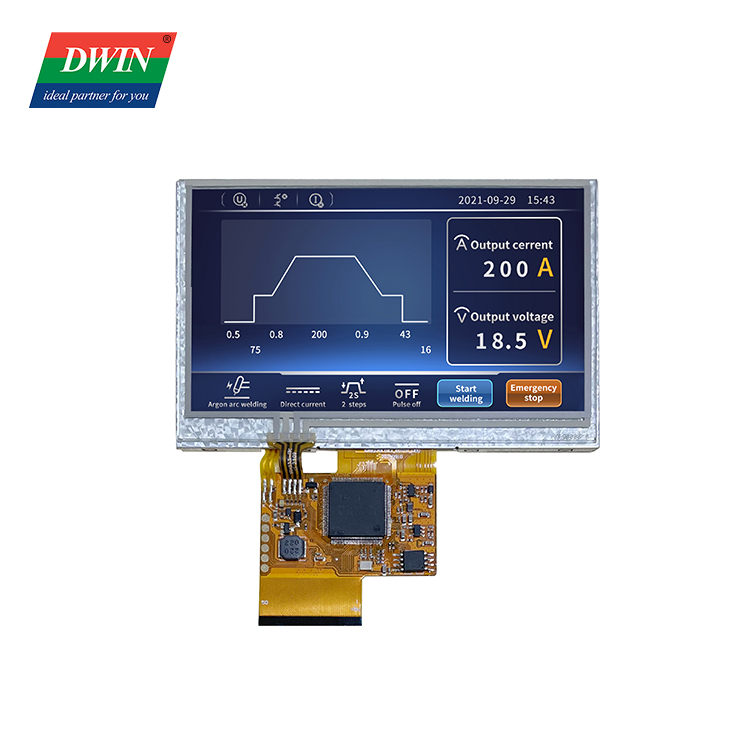

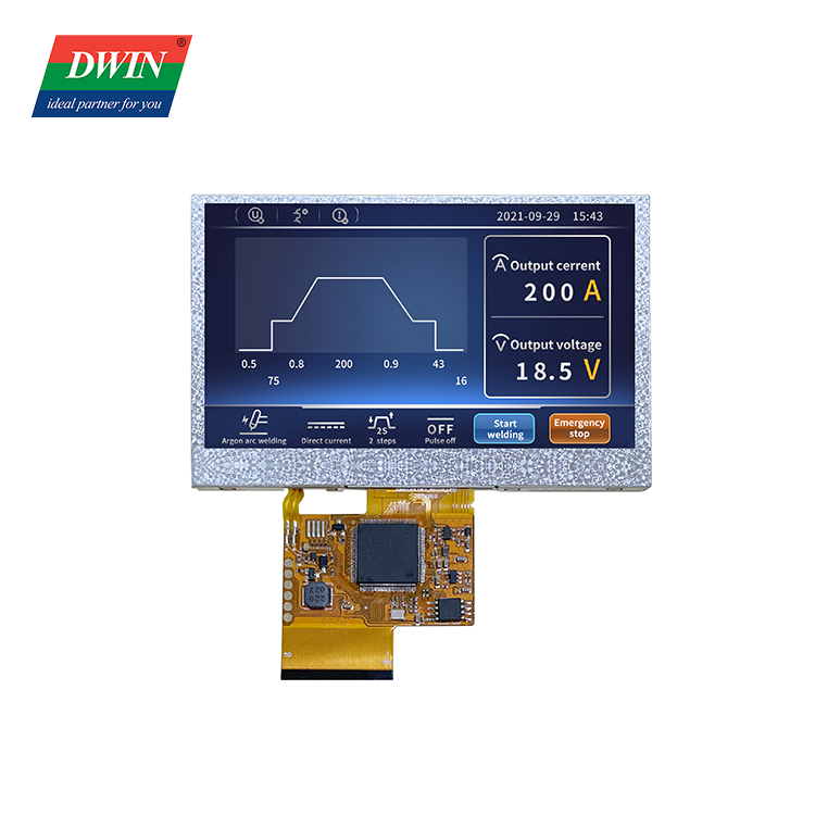
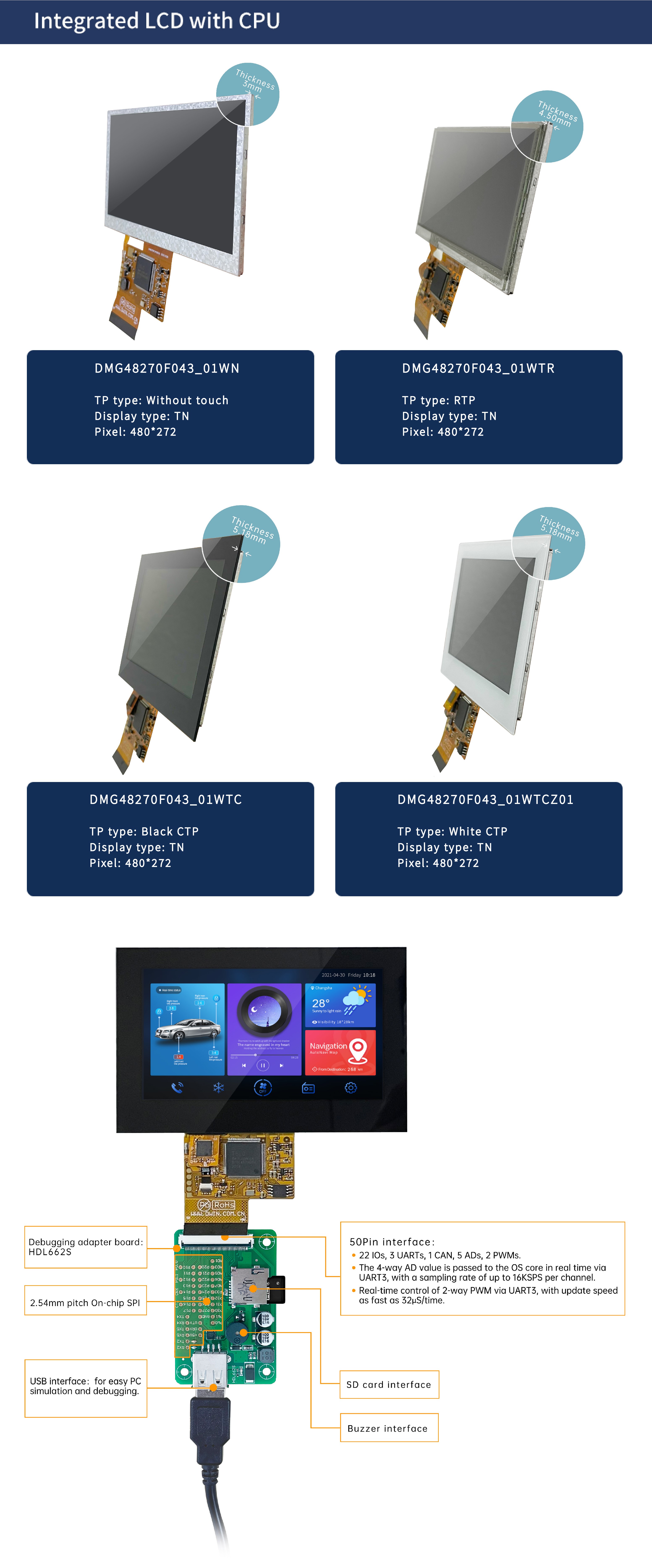
Specification
| Color | 262K colors | ||
| LCD Type | TN-TFT-LCD | ||
| Viewing Angle | Normal viewing angle, typical value of 70°/70°/30°/40°(L/R/U/D) | ||
| Display Area(A.A) | 95.04mm (W)×53.86mm (H) | ||
| Resolution | 480×272 | ||
| Backlight | LED | ||
| Brightness | DMG48270F043_01WTC:200nit DMG48270F043_01WTCZ01:200nit DMG48270F043_01WTR:200nit DMG48270F043_01WN:250nit |
||
| Power Voltage | 3.6~5.5V, typical value of 5V | ||
| Operation Current | 190mA, VCC=5V, max backlight | ||
| 80mA, VCC=5V, backlight off | |||
| User interface | 50Pin_0.5mm FPC | ||
| Baudrate | 3150~3225600bps | ||
| Output Voltage | Output 1;3.0~3.3 V | ||
| Output 0;0~0.3 V | |||
| Input Voltage (RXD) |
Input 1;3.3V | ||
| Input 0;0~0.5V | |||
| Interface | UART2: TTL; UART4: TTL;( Only available after OS configuration) UART5: TTL;(Only available after OS configuration |
||
| Data Format | UART2: N81; UART4: N81/E81/O81/N82;4 modes (OS configuration) UART5: N81/E81/O81/N82;4 modes (OS configuration) |
||
| Pin | Definition | I/O | Functional Description |
| 1 | 5V | I | Power supply, DC3.6-5.5V |
| 2 | 5V | I | |
| 3 | GND | GND | GND |
| 4 | GND | GND | |
| 5 | GND | GND | |
| 6 | AD7 | I | 5 input ADCs. 12-bit resolution in case of 3.3V power supply. 0-3.3V input voltage. Except for AD6, the rest data is sent to OS core via UART3 in real time with 16KHz sampling rate. AD1 and AD5 can be used in parallel, and AD3 and AD7 can be used in parallel, which equals to two 32KHz sampling AD. AD1, AD3, AD5, AD7 can be used in parallel, which equals to a 64KHz sampling AD; the data is summed 1024 times and then divided by 64 to obtain a 64Hz 16bit AD value by oversampling. |
| 7 | AD6 | I | |
| 8 | AD5 | I | |
| 9 | AD3 | I | |
| 10 | AD2 | I | |
| 11 | 3.3 | O | 3.3V output, maximum load of 150mA. |
| 12 | SPK | O | External MOSFET to drive buzzer or speaker. The external 10K resistor should be pulled down to the ground to ensure that power-on is low level. |
| 13 | SD_CD | I/O | SD/SDHC interface,The SD_CK connects a 22pF capacitor to GND near the SD card interface. |
| 14 | SD_CK | O | |
| 15 | SD_D3 | I/O | |
| 16 | SD_D2 | I/O | |
| 17 | SD_D1 | I/O | |
| 18 | SD_D0 | I/O | |
| 19 | PWM0 | O | 2 16-bit PWM output. The external 10K resistor should be pulled down to the ground to ensure that power-on is low level. The OS core can be controlled in real time via UART3 |
| 20 | PWM1 | O | |
| 21 | P3.3 | I/O | If using RX8130 or SD2058 I2C RTC to connect to both IOs, SCL should be connected to P3.2,and SDA connected to P3.3 in parallel with 10K resistor pull-up to 3.3V. |
| 22 | P3.2 | I/O | |
| 23 | P3.1/EX1 | I/O | It can be used as an external interrupt 1 input at the same time, and supports both low voltage level or trailing edge interrupt modes. |
| 24 | P3.0/EX0 | I/O | It can be used as an external interrupt 0 input at the same time, and supports both low voltage level or trailing edge interrupt modes |
| 25 | P2.7 | I/O | IO interface |
| 26 | P2.6 | I/O | IO interface |
| 27 | P2.5 | I/O | IO interface |
| 28 | P2.4 | I/O | IO interface |
| 29 | P2.3 | I/O | IO interface |
| 30 | P2.2 | I/O | IO interface |
| 31 | P2.1 | I/O | IO interface |
| 32 | P2.0 | I/O | IO interface |
| 33 | P1.7 | I/O | IO interface |
| 34 | P1.6 | I/O | IO interface |
| 35 | P1.5 | I/O | IO interface |
| 36 | P1.4 | I/O | IO interface |
| 37 | P1.3 | I/O | IO interface |
| 38 | P1.2 | I/O | IO interface |
| 39 | P1.1 | I/O | IO interface |
| 40 | P1.0 | I/O | IO interface |
| 41 | UART4_TXD | O | UART4 |
| 42 | UART4_RXD | I | |
| 43 | UART5_TXD | O | UART5 |
| 44 | UART5_RXD | I | |
| 45 | P0.0 | I/O | IO interface |
| 46 | P0.1 | I/O | IO interface |
| 47 | CAN_TX | O | CAN interface |
| 48 | CAN_RX | I | |
| 49 | UART2_TXD | O | UART2(UART0 serial port of OS core) |
| 50 | UART2_RXD | I |
DMG10600T101_01W(Industrial grade)